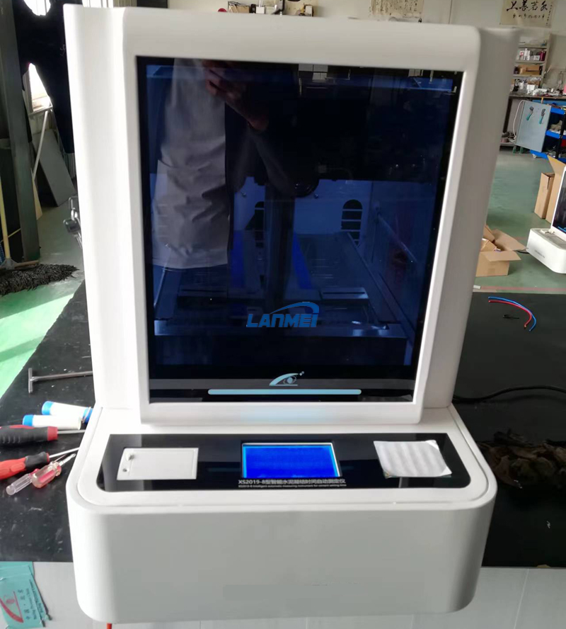


Cement Test Automatic Vicat Device
Automatic Vicat Machine provides a completely automatic method for determining the initial and final setting time of cements of mortar pastes.
The instrument is mainly composed of chassis bracket, LCD touch display, screw lifting system, sliding component, and displacement measurement system.
Feature:
- [One-key operation of position calibration] Fully automatic calibration, the machine will automatic calibrate the precision position after rough position calibration
- [Position memory storage] After completed calibration of each test position, the meter will automatic store data, no need to repeat calibration;
- [Automation of the measurement process] One-key operation, automatic measurement, and automatic lifting of the components after the measurement is completed;
- [Precise time control] 30 seconds of settlement time countdown precise control;
- [Judgment of test results] Judge the result data according to the requirements of the test specification, and prompt the operation;
- [Data storage] Standard consistency and setting time data are stored organically and uniformly, and can transfer and export;
- [Data interface] Support RS485 interface data output, import computer standard format test report software;
Technical Data:
1. Time control Display resolution: 0.1s
control precision: ≤±0.1s
2. Displacement Adapt high precision LVDT displacement sensor, split structure,
without friction when needle dropping
range: 0~50mm, display precision: 0.01s
Relative displacement accuracy: ≤±0.1mm
3.Storage data: 200 groups
4. Sliding component: 300g±1g(include needle and rod)
5. Data interface: RS485
6. Dimension: 390x310x575mm
7. Voltage: 220±10%VAC/50HZ
8. Power: 40w
9.Net weight: 12kg
- Test process and data storage relationship structure
When performing any test, you must first select the test [number] of the corresponding test piece, and then perform position calibration. The test data generated during the test is automatically loaded into the [data item] of the test [number].
Position calibration
- [Standard Consistency ]: Use test rods, put the glass plate on the disc platform.
- [Initial]: adopt the initial needle, put the glass plate on the disc platform.
- [Final]:
(1) Method1 : Adopt the initial needle, put the glass plate on the disc platform, put the mould on the glass plate, then put the glass plate on the mould (need to set the thick of glass plate).
(2) Method2: Adopt the initial needle, put the glass plate on the disc platform, put the mould on the glass plate, and use the upper edge of the test mold to calibrate the needle (need to set the thick of glass plate to zero).
- When change the needle or rod, need to calibrate the position of the corresponding test.
- When replacing the glass plate, if the thickness of the glass plate changes, you need to set the glass thickness and re-calibrate the position;
- When changing the test mold, if the height of mould changes, you need to set the height of the test mold and re-calibrate the position.
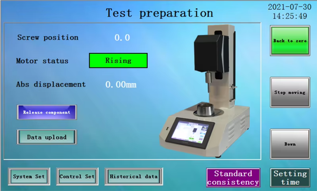
- The calibration interface is as follow.
- Standard consistency test
Step1. Assemble the standard rod. Lift the machine head, screw the standard test rod into the M8 thread at the lower end of the counterweight cylinder, and tighten it;
Step2. Calibrate the standard consistency position. Put the glass bottom plate on the test platform as shown in the figure and enter the [calibration interface] to calibrate the standard consistency position;
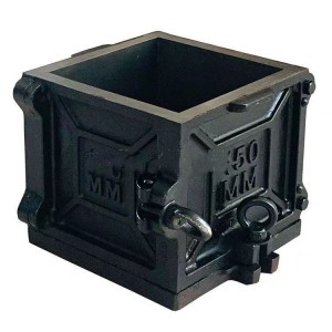
Step3. According to the specification, put the mixed cement paste into the mould which is placed on the glass bottom plate;
Step4. Place the mould well. Place the test mould equipped with the mixed pure slurry and glass plate on the test platform together, and set the center of the mould under the rod;
Step5. Start the test. The machine head drives the sliding component down to the upper surface of the cement paste, releases the component and measures the distance between the rod and the glass bottom plate. If the standard consistency meets the requirements after releasing the component for 30S (the distance between the rod and the bottom plate is 6mm±1mm), automatically pop up a dialog box, confirm the information according to the prompt, automatically calculate the standard consistency water consumption P (as a percentage of the cement quality), and store it.
- Setting time test
- Initial setting time test
Step1. Assemble standard needle. Lift the machine head, screw the standard test needle into the M8 thread at the lower end of the counterweight cylinder, and tighten it;
Step2. Calibrate the initial setting time position. Put the glass bottom plate on the test platform as shown in the figure and enter the [calibration interface] to calibrate the standard consistency position.
Step3. According to the specification, put the mixed cement paste into the mould which is placed on the glass bottom plate and curing it.
Step4. Place the mould well. Place the mold equipped with standard consistency pure paste and the glass plate under the test needle on the test platform together.
Step5. Start the test. The machine head drives the sliding component down to the upper surface of the cement paste, releases the component and measures the distance between the needle and the glass bottom plate. If the initial consistency state meets the requirements after releasing the component for 30S (the distance between the needle and the bottom plate is 4mm±1mm), automatically pop up a dialog box, confirm the information according to the prompt, automatically record the initial setting time and store it.
2.Final setting time test
Step1. Remove the mould after finished the initial setting time test, Turn over 180°, put the large end of the diameter upwards and the small end downwards on the glass bottom plate, and then put it in the curing box to continue curing, preparing for the final setting time measurement.
Step2. Assemble standard needle, Lift the machine head, screw the standard test needle into the M8 thread at the lower end of the counterweight cylinder, and tighten it.
Step3. Calibrate finial setting time position, put the glass bottom plate on the test platform as shown in the figure, place the mould on the glass bottom plate, and then place another glass bottom plate on mould, enter the [calibration interface], carry on the final setting time position calibration.
Step4. Place the mould well. Place the mold equipped with standard consistency pure paste and the glass plate under the test needle on the test platform together.
Step5. Start the test. The machine head drives the sliding component down to the upper surface of the cement paste, releases the component and measures the distance between the needle and the glass bottom plate. If the final consistency state meets the requirements after releasing the component for 30S (the distance between the needle and the bottom plate is 4mm±1mm), automatically pop up a dialog box, confirm the information according to the prompt, automatically record the final setting time and store it.